|
be.audiophil
|
 |
« Reply #1980 on: November 26, 2019, 07:14:58 PM » |
|
A different record player is used with the 2 carts which I've mentioned. The same thing happens..
A few different record was played to check. of course, the pops happen at different times but still, they're there.
I'll be buying some new tubes this weekend to swap out the tubes to check if the tubes have problems. Hmm, you were questioning whether the phono stage could have been overloaded by the track of this specific record. With all that changes made you got proof that itmight not be linked to the turntable, the tonearm, the cartridge but did not narrow it down whether it´s linked to the phonostage or the specific record. Thus I´m asking again: What happens with a different record played on that turntable with that EAR clone phonostage? What happens when no record is played? Furthermore Jessica asked for some measurements. Can you please report what numbers you got? By the way: Had a look at the video. Behaviour of you poweramp looks strange. |
|
|
|
|
 Logged
|
|
|
|
terfyo
Member

 Offline Offline
Posts: 13
|
|
« Reply #1981 on: November 27, 2019, 04:07:13 PM » |
|
Hmm, you were questioning whether the phono stage could have been overloaded by the track of this specific record. With all that changes made you got proof that itmight not be linked to the turntable, the tonearm, the cartridge but did not narrow it down whether it´s linked to the phonostage or the specific record.
Thus I´m asking again: What happens with a different record played on that turntable with that EAR clone phonostage? What happens when no record is played?
Furthermore Jessica asked for some measurements. Can you please report what numbers you got?
By the way: Had a look at the video. Behaviour of you poweramp looks strange.
Hi be.audiophil, Had my tubes swapped out today completely, all 3, one by one, to check if the tubes had problems. Well, with after replacing 1 by 1 till all 3 are replaced, the problem still persists. Ok, back to what you have mentioned, I have tried a few different records, the same problem happens. In my opinion, the phonostage has a problem, as I have played the same record with a different phono, this popping doesn't happen. Regarding the video of the poweramp, the lights shoot up all the way to full bias when there's a pop. I saw Jessica's request for a few measurements, but i do not exactly know how to get the measurements even though I have a DMM. Refer to the image below.  |
|
|
|
|
Logged
|
|
|
|
|
be.audiophil
|
|
« Reply #1982 on: November 29, 2019, 02:02:47 PM » |
|
Had my tubes swapped out today completely, all 3, one by one, to check if the tubes had problems. Well, with after replacing 1 by 1 till all 3 are replaced, the problem still persists. That´s what I was already expecting. The issue looks like you got a motorboating issue what´s not familiar with the PCB. Means that there´s most probably an issue with build quality or defect components that needs higher knowledge about electronics and tubes to be found and eliminated. I saw Jessica's request for a few measurements, but i do not exactly know how to get the measurements even though I have a DMM. Facing this issue it becomes hardly impossible to help you by posts in a forum. There should be found someone with the right knowledge about electronics and tubes who is located near you and willing to help and to eliminate all other issues with your build (orientation of the PCB and transformer in the case, length of cabling, earthing, separating PSU and phono circuit, etc.) in order to make this a good sounding and working build. Where do you come from? |
|
|
|
|
Logged
|
|
|
|
fasterbyelan
Cotswold Meet
Member
Offline
Age: 62
Location: Towcester, UK
Posts: 1,778
"If the first watt sucks, who wants another one?"
|
|
« Reply #1983 on: November 29, 2019, 05:28:16 PM » |
|
Plenty of info regarding mototboating on the net |
|
|
|
|
Logged
|
KarlLenco -cause it's got soul! My audio world here_______________________________________________________________________________________________
|
|
|
terfyo
Member
Offline
Posts: 13
|
|
« Reply #1984 on: November 29, 2019, 05:58:43 PM » |
|
Hi all,
I'm from Singapore.
Well, I've borrowed a unit from a friend, who has a unit built by a professional in tubes, with a wealth of knowledge. I've just tested the unit with the same track and guess what, there's the same issue.
I rest my case.
Anyway, I found out also that the supplier gave me 4 pieces of 220k resistors when the required is 330k. Damn! I'm making a complaint to Douk Audio.
TL
|
|
|
|
« Last Edit: December 22, 2019, 01:23:45 AM by Chris65 »
|
Logged
|
|
|
|
Irate
Member
Offline
Location: London UK
Posts: 85
|
|
« Reply #1985 on: December 18, 2019, 12:55:31 PM » |
|
I am rebuilding my 824 clone and was going to make some improvements, replace electrolytic caps with films and get a nicer output cap (the 1uf one) but have been quite pleased when replacing a coupling cap (in power amp) and output cap (in pre amp) with transformers and wondered if it would be possible to replace the output cap with a transformer, any one tried it or is it a bad idea?
Cheers
|
|
|
|
|
Logged
|
|
|
|
Taso
Member
Offline
Location: italy
Posts: 43
|
|
« Reply #1986 on: December 22, 2019, 12:12:00 AM » |
|
Hi, greetings from Italy! I also own a clone!  I wanted to ask you if you have an electrical diagram of the power supply and the pre phono..where the numbers of the relative components are also written..example ... c3 .... r5 ... r6 ... etc. I ask to be able better interpret the changes and improvements mentioned in this discussion. When you say .. I changed r3 ... or c6 ... etc ... I have another type of pcb both of the valves and of the power supply .. I can't understand what you are referring to. Thank you! My clone:     |
|
|
|
|
Logged
|
|
|
|
Jessica_K
Member
Offline
Age: 71
Location: Nr Portsmouth UK
Posts: 842
|
|
« Reply #1987 on: December 22, 2019, 10:46:50 AM » |
|
Hi Taso,
Welcome to LH
There are a number of schematics on this and the other EAR thread, the one on page 18 of this thread may be of assistance, it’s a bit blurry but I think you can make the parts out
All the best
Jessica xx
|
|
|
|
|
Logged
|
Linn/Vinyl Passion LP/VP12, Audiomods S6, ART 9xa, GL75, Linn Ittok, ST33sa
Alpha2delta PS1, PSU1's Phono, LL1931 SUT’s. Alpha2delta PRE1, Transcription audio heaven 211 (211 SET)
PMC GB1,s
|
|
|
Andrew.R
Member
Offline
Location: Wakefield, England
Posts: 770
|
|
« Reply #1988 on: December 22, 2019, 11:13:48 AM » |
|
Hi, greetings from Italy! I also own a clone! I wanted to ask you if you have an electrical diagram of the power supply and the pre phono..where the numbers of the relative components are also written..example ... c3 .... r5 ... r6 ... etc. I ask to be able better interpret the changes and improvements mentioned in this discussion. When you say .. I changed r3 ... or c6 ... etc ... I have another type of pcb both of the valves and of the power supply .. I can't understand what you are referring to. Thank you! My clone: Welcome, very neat! |
|
|
|
|
Logged
|
I own Wakefield Turntables - Specialists in Lenco Restorations (PM me)!
|
|
|
Thunders1988
Member
 Online Online
Age: 36
Location: Belgium
Posts: 282
Conquistador of the useless.
|
|
« Reply #1989 on: December 23, 2019, 03:46:10 PM » |
|
So over the weekend I put together my 834 clone using the ZeroZone PCB’s. Made my own PSU consisting of a Hammond 369AX Transformer, a 154E choke and a 16+16uF cap. I was thinking about using a tube rectifier, but when I had drilled all the holes in the chassis I found out there’s no 5 volt tap on that transformer.  Too late. Already had the hole for the GZ32 tube drilled as well so I decided I might just roll with it and crack a bad octal pin tube, solder a bridge rectifier across the pins and check if I could get away with it. Heaters of the ECC83’s are directly off of the transformer. No rectification. B+ is a (un?)healthy 338Vdc. Everything works fine. All voltages measured on the tubes is within datasheet specifications. Heatervoltage on all 3 tubes 6.23Vac (pin 4&5 jumpered, running heaters centertapped through pin 9). Tube 1: Platevoltages 223Vdc Heater-Kathode 40Vac T2: Platevoltages 68Vdc H-K 40Vac T3: Platevoltages 90Vdc H-K 40Vac The transformer is running a little warm to the touch. Have the slightest concern about that... I tried lowering the B+ by grounding the centertap on the transformer trough a pair of 1N5343 zener diodes but the drop was way too much. Down to about 150Vdc. Any comments or ideas? For now, I’m leaving the heater- and HT centertap floating.  |
|
|
|
|
Logged
|
Mathias
|
|
|
Firebottle
Member
Member
Offline
Location: Dudley, West Midlands
Posts: 369
|
|
« Reply #1990 on: December 23, 2019, 05:08:13 PM » |
|
Many transformers are specified with up to 55 degree temperature RISE.
If you can keep your hand on it (about 50 degrees or less) then it will be fine.
|
|
|
|
|
Logged
|
I'm Alan, an avid valve amp designer.
I don't bite, ask any question you like.
|
|
|
JacquesD
Member
Offline
Age: 73
Location: Ghent (Belgium)
Posts: 515
|
|
« Reply #1991 on: December 23, 2019, 05:31:49 PM » |
|
So over the weekend I put together my 834 clone using the ZeroZone PCB’s. [...]but when I had drilled all the holes in the chassis I found out there’s no 5 volt tap on that transformer. If there's a little room under the chassis, you could add a small transformer providing 5V (at least 2.3A -- careful with the orientation) to heat that GZ32? Rectifying with a tube will likely give a lower B+ plus the benefits (and drawbacks) of tube rectification. Are you happy with the ZeroZone PCBs? I have a pair waiting for some work, one of the good intentions for the next year  Success, |
|
|
|
|
Logged
|
Jacques
Mostly listening to (modded) vintage equipment
|
|
|
Thunders1988
Member
Online
Age: 36
Location: Belgium
Posts: 282
Conquistador of the useless.
|
|
« Reply #1992 on: December 28, 2019, 10:10:34 AM » |
|
Hi Jacques,
I considered a small 5V transformer, but there’s just no room.
You can always make a full wave diode rectifier and put the choke in front of the first capacitor. This too, will lower B+.
The ZZ boards are OK for the money. Just make sure you don’t need to un-solder something. The tracks lift quite easily.
Happy holidays and have fun!
|
|
|
|
|
Logged
|
Mathias
|
|
|
Ollvid72
Member
Offline
Posts: 2
|
|
« Reply #1993 on: January 10, 2020, 10:43:31 PM » |
|
Dear All, as mentioned earlier in this thread http://www.lencoheaven.net/forum/index.php?topic=20935.0I´ve ordered a pcb set recently because of interest and for evaluation. Signal PCB is an exact copy of the original EAR 834p schematic which I´ve diy ed some years ago; power supply pcb is slightly but not dramatically changed. 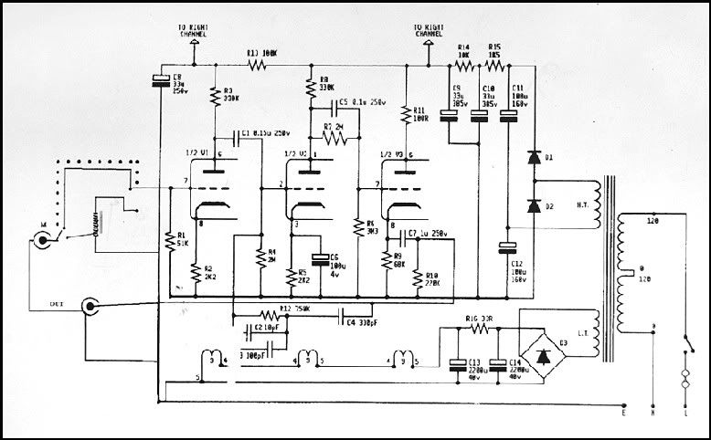 I´d changed wiring of tube socket in order to use russian 6N2-P tubes instead of 12AX7 aka ECC83. Converting the wiring will get you lucky in using tubes that are more likely ECC808 and really cheap to source in good and good NOS quality while sourcing ECC83 in good and in good NOS quality gets more and more expensive. For this improvement it´s only necessary to rework heater wiring and to ground pin 9 which is draging the screen between triode halfs to ground with reducing crosstalk and increasing channel separation. As allways: Pictures rules           How long did it take to solder the kit and what did I have to source separately? Within one evening one should be able to solder the complete kit The pcb kit came with all resistors, diodes/ rectifier and silver mica for RIAA network and one 10µF/ 250V electrolytics used in power supply also. I´ve ordered the mains transformer also from this seller. Thus I sourced the following components - 2 pieces of 330 µF/ 450V electrolytics - 9 pieces of 47µF/ 400V electrolytics (luckily did have about 100 pieces in stock) - 2 pieces of 1,0 µF/250V MKP (luckily did have Mundorf M-Cap I normally do not use and some Solen and Audyn in stock) - 2 pieces of 0,15 µF/ 250V MKP (luckily did have Mundorf M-Cap I normally do not use and some Solen and Audyn in stock) - 2 pieces of 0,1µF/ 250 V MKP (luckily did have Mundorf M-Cap I normally do not use and some Solen and Audyn in stock) - 3 pieces 4700µF/ 16V Panasonic FC electrolytics (luckily did have some in stock) - 3 pieces 6N2-P tubes (luckily did have some in stock) - 3 pieces of higher quality tube sockets (luckily did have some in stock) - 4 pieces of RCA jacks - some wires - one Fuseholder - mains jack Now I´m waiting for the enclosure http://www.ebay.de/itm/DYT-1-Full-Aluminum-Enclosure-preamp-case-Power-amp-box-DIY-PSU-chassis-/121139092508?hash=item1c3473dc1cLet´s talk about costs: Building that kit should be possible to finish for less than € 400; with using higher quality parts and matching parts as I did it should be finished for less than € 550. Is it posibuild that you have the diagram off the ERA 834p you have build and maybe a part list i have ordet this kit on eBay and would like to make one like youres |
|
|
|
|
Logged
|
|
|
|
PatrickJones
Member
Offline
Posts: 5
|
|
« Reply #1994 on: January 23, 2020, 12:51:01 PM » |
|
Hi everyone, long time lurker, first time poster...
I've taken the leap and built an EAR 834p with the Xuling board and Jessica's PSU and have loved every second of my first DIY project! The one thing that's confusing me and I'm hoping someone may be able to advise on is that while the chassis and PSU are both run to ground via the IEC's earth post, there's nothing earthed on the signal side of things. The Xuling board has a 4 way ground pad - should each of these be run to the star ground on the PSU or left alone? The whole thing works and sounds absolutely fantastic with no hum at all, but I'm concerned that it may not be correct / safe at the moment. My tonearm is a Rega RB303 and if I connect the grounding spade to the EAR chassis I then get significant hum (presumably because it's at a different potential to the board?), which suggests things aren't correct.
Can anyone advise on what I should be doing, or if it's safe to leave as is with the ground on the tonearm unconnected?
|
|
|
|
« Last Edit: January 23, 2020, 05:17:23 PM by PatrickJones »
|
Logged
|
|
|
|
|

