Taso
Member

 Offline Offline
Location: italy
Posts: 43
|
 |
« Reply #2025 on: April 22, 2020, 02:28:48 AM » |
|
Hi Taso,
......
Jessica xx
thanks Jessica for all the advice, I'm implementing them.  |
|
|
|
|
 Logged
|
|
|
|
Jessica_K
Member
Offline
Age: 71
Location: Nr Portsmouth UK
Posts: 842
|
|
« Reply #2026 on: April 22, 2020, 08:38:12 AM » |
|
Dear friends,
I have recieved the EAR PCB from Douk and I am looking at populating it.
The information gathered around this specific design is of great help.
Thanks to all you guys out there that have contributed your knowledge.
For a lot of us, it can be quite easy to lose track of everything that has to be done, so all the help is appreciated.
I have been reading through the many pages and if I understand correctly, there are two main paths to be followed regarding values for those RIAA capacitors in the feedback loop.
One i've seen in various schematics (in Douk as well) using a 330pF followed by a 110pF capacitor.
And another proposal (i might be wrong but I think originally by Robert), that replaces the 330pF with a 300pF and the 110pF with a 100pF.
Please correct me on the above if I am wrong.
Now if anyone has used both, can they describe what's the difference in sound?
I was ready to try both sets of values, but those silver MICA are not exactly cheap, so I thought I ask you guys.
Thanks in advance!
Hi Mamakasou, The change in the RIAA response is an improvement over the original values that make the amp a little dull, I do not know the modern evolution of the production EAR as the clones are based on a very early schematic and improvements in response may have evolved. I have tried the value changes and it is a flatter response as measured. Below is a snippet of the values and is very flat from 100Hz to 20kHz  The resistor R8 controls the low frequencies of the response the value is very dependent on the tubes, the higher the value the more base lift, in the example above a 820K is used and is based on using the Thorston mod of removing the filter between V2 an V3. If this is not removed then that filter rolls off the low frequencies and the original value is closer to requirements. You can experiment with the value of R8 if the amp sounds boomie or light on base Jessica xx |
|
|
|
|
Logged
|
Linn/Vinyl Passion LP/VP12, Audiomods S6, ART 9xa, GL75, Linn Ittok, ST33sa
Alpha2delta PS1, PSU1's Phono, LL1931 SUT’s. Alpha2delta PRE1, Transcription audio heaven 211 (211 SET)
PMC GB1,s
|
|
|
Taso
Member
Offline
Location: italy
Posts: 43
|
|
« Reply #2027 on: April 22, 2020, 11:04:59 AM » |
|
Hi Mamakasou,
....
The resistor R8 controls the low frequencies of the response the value is very dependent on the tubes, the higher the value the more base lift, in the example above a 820K is used and is based on using the Thorston mod of removing the filter between V2 an V3. If this is not removed then that filter rolls off the low frequencies and the original value is closer to requirements. You can experiment with the value of R8 if the amp sounds boomie or light on base
Jessica xx
Forgive me but I don't understand English well. The higher the R8 value, the more low frequencies? The lower the R8 value, the more the bass are cut off? In my version instead of the filter between v1 and v2 ... I only have a 100ohm R. Thank you |
|
|
|
|
Logged
|
|
|
|
Jessica_K
Member
Offline
Age: 71
Location: Nr Portsmouth UK
Posts: 842
|
|
« Reply #2028 on: April 22, 2020, 11:43:38 AM » |
|
Yes Taso,
R8 higher provides more bass, lower less bass. The idea is to have it as flat as possible. There is no rumble filter if the Thorsten mode is made so this should not be set to lift bass beyond flat as it can then produce a lot of subsonics (seen as speaker cones flapping) due to recordings and or turntable rumble. Some subsonics are acceptable if due to bad pressings as you could be reducing your base response for the good pressings but must not be always present. Always better to err on reduced bass as long as it is acceptable. You will have to use your eyes and ears if you do not have a spectrum analyser, if you are lucky to own one as I do, then you can set the value precisely.
Jessica xxx
|
|
|
|
|
Logged
|
Linn/Vinyl Passion LP/VP12, Audiomods S6, ART 9xa, GL75, Linn Ittok, ST33sa
Alpha2delta PS1, PSU1's Phono, LL1931 SUT’s. Alpha2delta PRE1, Transcription audio heaven 211 (211 SET)
PMC GB1,s
|
|
|
mamakasou
Member
Offline
Posts: 289
|
|
« Reply #2029 on: April 23, 2020, 03:33:03 PM » |
|
The resistor R8 controls the low frequencies of the response the value is very dependent on the tubes, the higher the value the more base lift, in the example above a 820K is used and is based on using the Thorston mod of removing the filter between V2 an V3. If this is not removed then that filter rolls off the low frequencies and the original value is closer to requirements. You can experiment with the value of R8 if the amp sounds boomie or light on base Jessica xx Dear Jessica, Thanks for the reply and for clarifying this to me a bit further. As suggested, I'll omit the filter between V2 and V3 (C5, R6, R7 in the following schematic). Tubes will be either Sovtek, JJ Electronics or something on that lines. No NOS tubes planned for this build. So, I will also try values of 1MΩ and 820kΩ for R8 (R4 in the following schematic with 2MΩ original value). 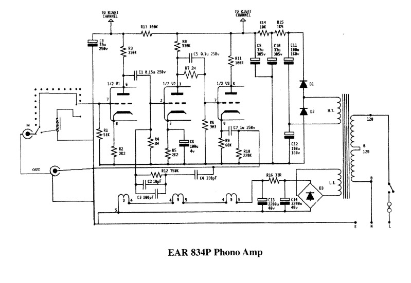 Also, in reference to the schematic you've provided my idea is to try: 100pF for C7 300pF (a single capacitor) in place of both C4, C6 787kΩ (single Holco resistor) in place of both R7, R10 Do you think these are a good choice? |
|
|
|
« Last Edit: April 23, 2020, 05:30:49 PM by mamakasou »
|
Logged
|
|
|
|
Jessica_K
Member
Offline
Age: 71
Location: Nr Portsmouth UK
Posts: 842
|
|
« Reply #2030 on: April 24, 2020, 11:03:22 AM » |
|
100pF for C7
300pF (a single capacitor) in place of both C4, C6
787kΩ (single Holco resistor) in place of both R7, R10
Do you think these are a good choice?
C4/C6 are combined to use preferred values that are easy to find, a single 300pf cap is very useable if you get one in silver mica and 1% max tolerance. Same with the R7/R10 combo, using a 787k is about 0.4% error without taking in the error in the resistor it’s self, however the response difference is low and if you can get 0.1% resistors that will be useable Jessica xx |
|
|
|
|
Logged
|
Linn/Vinyl Passion LP/VP12, Audiomods S6, ART 9xa, GL75, Linn Ittok, ST33sa
Alpha2delta PS1, PSU1's Phono, LL1931 SUT’s. Alpha2delta PRE1, Transcription audio heaven 211 (211 SET)
PMC GB1,s
|
|
|
|
|
Jessica_K
Member
Offline
Age: 71
Location: Nr Portsmouth UK
Posts: 842
|
|
« Reply #2032 on: April 25, 2020, 05:50:18 PM » |
|
Those diodes are perfect for the job. There is very little current required so 3A is no issue. Snubbers are not required, I never use them and they are difficult to make work as they are very hard to fit correctly so they have the effect they are trying to do, hence a previous comment I made on them being a black art.
Jessica xx
|
|
|
|
|
Logged
|
Linn/Vinyl Passion LP/VP12, Audiomods S6, ART 9xa, GL75, Linn Ittok, ST33sa
Alpha2delta PS1, PSU1's Phono, LL1931 SUT’s. Alpha2delta PRE1, Transcription audio heaven 211 (211 SET)
PMC GB1,s
|
|
|
Taso
Member
Offline
Location: italy
Posts: 43
|
|
« Reply #2033 on: April 25, 2020, 06:41:14 PM » |
|
Yes. I remember well when you used the definition "black art". I would say it is perfect ..ok .. I buy these 24 diodes !! so I solve the problem at the root. Have a nice weekend!  |
|
|
|
|
Logged
|
|
|
|
mamakasou
Member
Offline
Posts: 289
|
|
« Reply #2034 on: April 29, 2020, 12:58:30 AM » |
|
Thanks a lot Jessica!
Helpful as always.
|
|
|
|
|
Logged
|
|
|
|
terfyo
Member
Offline
Posts: 13
|
|
« Reply #2035 on: May 06, 2020, 05:55:30 PM » |
|
Hi all,
Just got a kaput transformer giving out smoke amidst the Covid-19 situation.
I've got to bring in a new transformer to replace the dead one.
Before I do, I would like to confirm the rating of the transformer, and would also like to know if the transformer that I've put in is not sufficient.
My current dead transformer R-core
Input 220VAC
Output 280V/0.08A & 6.3V/2A
I would like buy a replacement, looks better, EI type.
Input 220VAC
Output 280V/0.035A & 280V/0.035A & 6.3V/4.7A.
So with this new transformer, I would parallel the 280V outputs X2 and get 0.07A out from them.
Please advise if this current rating is sufficient for the 834?
Thanks in advance
Tim
Sent from my SM-N975F using T***talk
|
|
|
|
|
Logged
|
|
|
|
Jessica_K
Member
Offline
Age: 71
Location: Nr Portsmouth UK
Posts: 842
|
|
« Reply #2036 on: May 06, 2020, 10:19:22 PM » |
|
That output is sufficient to drive the 280V of the EAR it only requires about 10mA out of the 70mA available
Jessica xxx
|
|
|
|
|
Logged
|
Linn/Vinyl Passion LP/VP12, Audiomods S6, ART 9xa, GL75, Linn Ittok, ST33sa
Alpha2delta PS1, PSU1's Phono, LL1931 SUT’s. Alpha2delta PRE1, Transcription audio heaven 211 (211 SET)
PMC GB1,s
|
|
|
terfyo
Member
Offline
Posts: 13
|
|
« Reply #2037 on: May 07, 2020, 02:49:15 AM » |
|
That output is sufficient to drive the 280V of the EAR it only requires about 10mA out of the 70mA available
Jessica xxx
Thanks Jessica. Am always looking forward to your advice on this particular build. |
|
|
|
« Last Edit: May 07, 2020, 03:39:20 AM by Chris65 »
|
Logged
|
|
|
|
Taso
Member
Offline
Location: italy
Posts: 43
|
|
« Reply #2038 on: May 10, 2020, 02:12:30 AM » |
|
Here I am! I'm sorry but I'm back!  I mounted the SIC on the anode and saw the improvements. Jessica was obviously right. Since I like SIC very much ... can I also use them for filaments? SIC on filaments is the best solutions? Thanks! |
|
|
|
|
Logged
|
|
|
|
Jessica_K
Member
Offline
Age: 71
Location: Nr Portsmouth UK
Posts: 842
|
|
« Reply #2039 on: May 10, 2020, 07:25:10 AM » |
|
Note on using SiC rectifiers on the filament supply. Their forward voltage drop is high, if you are using 6.3V and a regulator there is not enough voltage left to drive it. If you are not using a regulator such on the dork supply then OK, if you are using 12.6V then there is not a problem Using a regulator
Jessica xxx
|
|
|
|
|
Logged
|
Linn/Vinyl Passion LP/VP12, Audiomods S6, ART 9xa, GL75, Linn Ittok, ST33sa
Alpha2delta PS1, PSU1's Phono, LL1931 SUT’s. Alpha2delta PRE1, Transcription audio heaven 211 (211 SET)
PMC GB1,s
|
|
|
|

