Good evening ladies and gentlemen my name is Ian and I am a 59 year old Tinbasher who professes to have limited Audiophile qualifications, No design skills in the area of electronics, abyssal spelling capacity but who has spent a lifetime in metalwork. I have recently passed my Architectural Metalwork Company (Satin Stainless Fabrications Ltd if you would like to browse some of London's most prestigious projects) onto my son and have decided to finally do the things in life I've always wanted to but never had the time for...
In my younger days I got somewhere near 40% the way through building a 5 inch Gauge Britannia Steam Locomotive after building a small steam reciprocating engine at the age of 14/15 at school (see Picture, now looking its full 40 odd years old being stuck in the garage) but before reigniting the steam power projects I got hooked on this forum and thought... Gizza a job I can do that....
The first thing I noticed is what appeared to be some rather well enlightened souls commenting that ideally the motor and electrics be positioned as far away from the arm/cartridge as possible. I took note that turning the motor 180 degrees and placing outside the footprint of the platter would result in the idler gear rotating in the opposite direction to what is required, Sooooo lets employ Two! idlers I pondered.
The following is a pictorial catalogue of the mock up and trial that I'm pleased to say actually works. The metalwork finish is not my normal high standard as I simply wanted to prove the "self-locking" mechanism of the 3no moving spindles/wheels. I also added a disengagement arm that Im happy to report works also. No Igus sleeve of flanged bearings are employed in this mock up but will be in the final production model that I'm am now starting. Igus staff are very helpful Btw and a meeting is planned regarding the main bearing in the next couple of weeks.
All the materials will be 316 grade 240 grit polished stainless steel and CZ108 240 grit polished and lacquered brass. It is my intension for the internals to mirror the high quality of the outside. The external finish will be a combination of stainless steel and Piano Black finish Ply/Mdf.
Anyway onwards and upwards as they say ...or fall flat on my face....

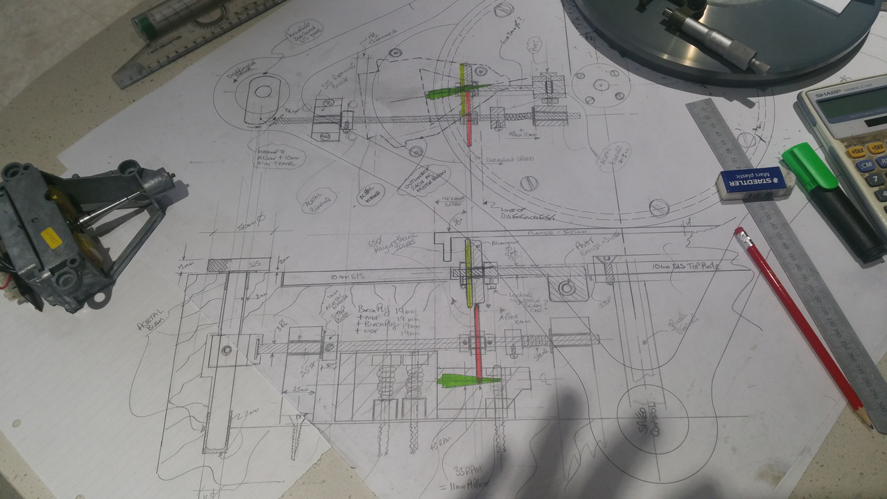
First scribbles


First off lets knock some motor mounting pins up out of some grade 8.8 bolts thats lying around the workshop

Laser cut motor mounting plate and brass support legs

Fix the motor in position


Disengagement arm, supports and Idler wheel


That's a heavy top plate but will be scrap when the stainless steel one is waterjet cut

Platter Idler wheel with drop down mounting


Place the platter on

Underside view

offer the motor mounting plate up to the idlers


And the Disengagement arm and idlers all work ... So far so good


I Have a video of the motor powered up and working so will post that latter
Many Thanks for a great forum.
Ian J


