Der Herr N.
Member

 Offline Offline
Location: Wien
Posts: 53
|
 |
« on: April 14, 2011, 06:19:10 PM » |
|
This will be my first build. I would like to share some underlying ideas with everyone befor I even start. I am aware that theory and practice don’t necessarily coincide in a system as complex as a phonograph. Nevertheless, here are some thoughts. I have read (and still am reading) a lot on Lenco Heaven, although by no means everything. If my thoughts duplicate anything, please forgive me. This build was inspired by a build I studied late a couple nights ago. It uses a tube braced to the plinth to support the platter bearing. It was late, so I forgot to write down the esteemed author but would like to give him full credit. The IssuesA. Forces 1. StaticMostly the weight of the platter as it bears down onto the thrustplate. This downward force is counter acted by the top-plate, to which the platter bearing is mounted. Since the load (3.7 kgs) is concentrated on a pretty small area of the pan, deflection occurs. Not good. Supporting the pan with a contact area as large as possible is a solution, although not a very controlled one. Supporting the platter bearing directly at the source strikes me as a rather more elegant and positively defined solution. 2. DynamicThe dynamic rotational force of the platter becomes a static load as soon as the platter has reached equilibrium, which as we know is pretty immediately. If paranoid (I will be), one could horizontally brace the new platter bearing support. B. Vibrations Vibration=energy. We need to either convert it into work or heat to get rid of it. 1. From motorAssuming 1500 rpm the natural frequency of the motor is 25 Hz (1500/60=25). Structual damping (free or constrained) can easily move this frequency outside the audible band. 2. From Main bearingAt a speed of 33.34 rpm, its natural frequency therefore can be assumed as .56 Hz, nothing to worry about, I would think. C.Sensible use of resources The solid plinths so successful (and therefore so popular, or is it the other way around?) could be a waste of material, if we find a better way to get rid of vibrations and solve issues of support. The solid plinths remind me of SUVs, although unlike them it might be the ultima ratio. D. Outward appearance Issues of domestic approval and ridicule. No need to elaborate. The ProposalFrom the bottom up. Take a bottom plate with adjustable feet (ideally three, practically four), designed to store and dissipate the vibrations generated by the motor. CLD or mass is the question here. Maybe a combination? CLD we can calculate (I don’t know how to, yet, but I’m working on it) to move the frequency where it doesn’t bother us, mass seems hit and miss (but maybe someone here can calculate it). Part of this layered bottom plate, its top layer, is a sheet of metal (aluminum would be preferred, I think) with a, let’s say 80 mm long tube welded to it. At the top rim of the tube the bearing will rest. The four existing threaded fixing points in the top-plate would be used to rigidly mount four posts with adjustable acorn nuts at the bottom. These four additional top-plate supports will simply rest on the bottom plate. (My quick drawings should explain this better). Done. One could leave it like that, or have fabric “curtains” all around. Domestic, safety and visual concerns will dictate an enclosure of sorts. 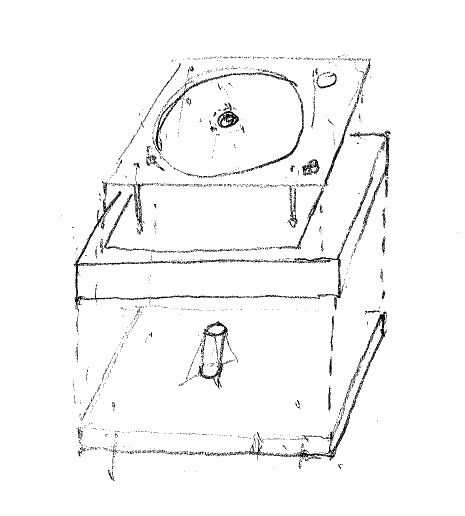 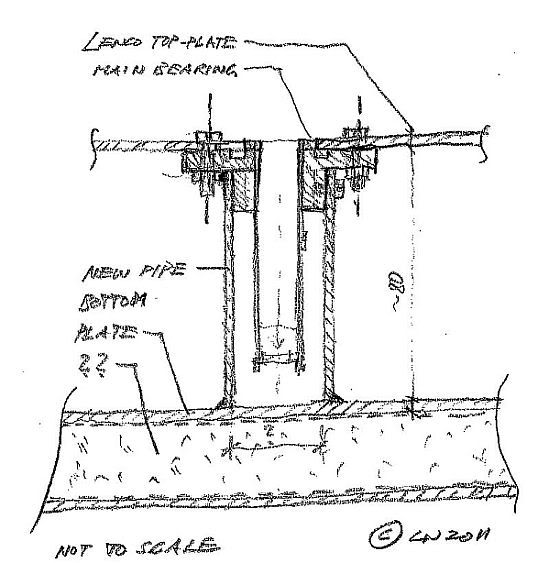 The four walls and the top piece of the enclosure can rest on the bottom plate, but may not touch the steel top-plate. They are not structural. The look will be much like the original players, a black bottom plate with a veneered plinth sitting on it. I like the look of the original more every day, I hope to aquire an original this weekend, which after restauration is going to become my reference point. So, in theory, all energy is stored and dissipated into the bottom plate which at the same time provides much needed improved structural support of the original parts. To avoid that the resulting voids do not become resonant chambers for any left over or not reckoned with vibrations, carefully designed absorbtion may need to be applied to all reflective surfaces. Only building it will tell. Carefully designed of course means only as much as absolutely necessary. What does the illustrious jury think, other than, go ahead, build it? |
|
|
|
« Last Edit: April 14, 2011, 06:28:26 PM by Der Herr N. »
|
 Logged
|
Leopold
Brought on by a simple twist of fate ... Bob Dylan
|
|
|
Johan
Member
Offline
Age: 64
Location: Helsingborg, Sweden
Posts: 1,119

|
|
« Reply #1 on: April 14, 2011, 07:25:35 PM » |
|
That might be a nice solution. But remember there are other vibration sources also; the idler wheel and its arm. I don't quite get the 25 Hz frequency of the motor. Well, I mean I get the computation, but what do I hear when I put a screwdriver between the motor and my ear? I don't think I can even hear 25 Hz.  I haven't tried anything like what you are proposing. I have only made plywood plinths, but I chose non-bulky ones, as I want to keep my decks close to the original ones. |
|
|
|
|
Logged
|
Johan
WL70 - ΨAΘIN MS-12B - Icon Audio ST40 - Fostex FF125wk Fonkens
|
|
|
Der Herr N.
Member
Offline
Location: Wien
Posts: 53
|
|
« Reply #2 on: April 14, 2011, 09:24:24 PM » |
|
Oh, I'm pretty sure you can hear 25 Hz  . The lowest key on a piano is 27.5 Hz to give you a frame of reference. Many people can hear as low as 15 or 16 Hz, but not many of the middle-aged crowd, especially if male, will hear above 14000 Hz ... |
|
|
|
|
Logged
|
Leopold
Brought on by a simple twist of fate ... Bob Dylan
|
|
|
Johan
Member
Offline
Age: 64
Location: Helsingborg, Sweden
Posts: 1,119
|
|
« Reply #3 on: April 14, 2011, 09:34:29 PM » |
|
Of course, you are right!  I now remember I hear rather low notes on the HF Test record. Must have messed something up! |
|
|
|
|
Logged
|
Johan
WL70 - ΨAΘIN MS-12B - Icon Audio ST40 - Fostex FF125wk Fonkens
|
|
|
ecosprog
Member
Offline
Age: 63
Location: Up the mountain, Spain
Posts: 2,429
|
|
« Reply #4 on: April 14, 2011, 09:40:17 PM » |
|
Leopold this is really interesting. I like seeing someone taking an original approach to a problem and I will be watching to see how this develops.
Keep us updated on any progress you make, and photos are always welcomed.
|
|
|
|
|
Logged
|
|
|
|
|
nic
|
|
« Reply #5 on: April 14, 2011, 10:25:14 PM » |
|
Leopold, Excuse the questions if they are dumb....  1. won't the original top plate flex? I know it's supported by the 4 points but still... 2. Am I right in thinking the motor and tonearm are attached to the top plate still? Perhaps some way of divorcing them would be good. You've gone to a lot of trouble to separate the platter/bearing after all. 3. 80mm doesn't sound like a lot, so how about a custom made bearing which is that long. So all in one. Of course your solution is an easier onto achieve (I think  ) 4. Alignment would be difficult but how about a modular/divided bottom plate that separated motor/top plate, bearing, tone arm? Once again apologies if these queries/suggestions are inane. |
|
|
|
|
Logged
|
|
|
|
Der Herr N.
Member
Offline
Location: Wien
Posts: 53
|
|
« Reply #6 on: May 12, 2011, 02:10:36 PM » |
|
So, following my plan layed out further up, I have progressed from Experimental set-up (top plate supported at edges of pan on three coffee cans) to Laboratory set-up no.1. Essentially, it is a fairly quick and dirty mock-up, to see in which direction this is going, and whether I should pursue this path, or just go with the tried and true ply or stone plinth. All my listening is currently done with my carefully alligned Shure M75EJ (standard Jico needle) at 2.4g, through a George Wright preamp, George Wright single ended 2A3 amps and single driver Moth Cicadas. Four threaded M4 stainless steel rods are screwed into the top plate threads. These stilts are adjustable via acorn nuts and countered with hexnuts. A steel tube is supporting the bearing from the underside. The idea is, not to have the massive weight of the platter essentially hanging from the center of the relatively thin top plate pan, causing considerable deflection of same. Instead, this load is supported by the steel tube and transferred to the bottom plate. Bottom plate is six layers of 5 mm hardboard, currently not bonded together. It’s something I had lying around and convenient to work with. Set-up is completely level (carefully checked with over-the-spindle type spirit level). The five points of contact with the bottom plate rest on 3 mm aluminum sheets on 2x2 cm rubber pads. The bottom plate rests directly on the frame of my wall support bracket, which is very securely (Hilti chemical anchors) bolted to a brick wall. 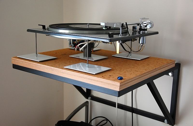 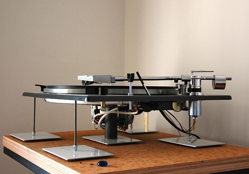 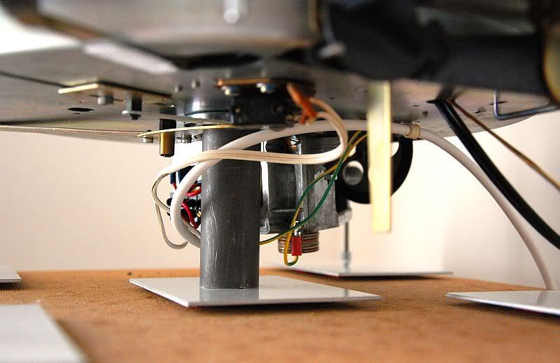 Other changes I have made to the original parts are: Bearing: Spindle meticulously polished to mirror surface with Wenol metal polish. Bearing surfaces cleaned, re-oiled. Steel ball replaced with ruby ball of same (5 mm) dia. Thrust plate replaced with teflon plate, void around ball packed w/ bearing grease. Filled bearing with Mobil 1. One peculiar thing about my (Italian made) bearing is, that they used three(!) Nylatron thrust plates in the factoy (blue paint over set screw was intact) to get the platter far enough away from the top plate. When I removed two of the plates it scraped the plate. Arm: The gap where the arm is decoupled filled with teflon plumbers tape (cf. dental floss tweak). Motor/Idler: Cleaned, oiled, centered, adjusted to virtually zero noise. Idler arm wrapped with teflon plumbers tape. Mass (stacked quarters held together w/ blue-tak) added to motor housing Compared to my stock L75 (disassembled, cleaned, lubed, dental flossed, plinth suspension blocked, cautious damping of plinth), the sound of the Lab1 is utterly relaxed, dead quiet. (Possibly a bit too relaxed, but I need to do more listening with varied program). Clearly more resolution/information than stock, while retaining all other virtues, with one big esception: there is noticably less foundation. Bass is there, what is there is exact, but its intensity is painfully diminished compared to stock L75. Voices emerge without any effort, no grain. On L. Cohens ‘Famous Blue Raincoat’ the intimacy and emotion is really intense. His voice whisper quiet (compared to the next track), really georgeous, satisfying stuff. Guitar beautiful. Same on other records, the small scale stuff works really well, touches me. The larger scale stuff (starting with band versus solo) is less satisfiying. This has always been somewhat of an issue in my system, in my room. With the stock Lenco, this was much less noticable, much more satisfying (always an advantage of competent lower resolution systems, it seems). One might say, that as I have brought the Lenco closer in resolution to my LP12, my old issues have returned.  I listened mostly at low volumes, but also some at higher volumes. At higher volumes the issues are less pronounced than at the lower volumes I am used to (listening at night while children sleep), which are really enjoyable with the stock L75. Real bass impact however (mind you, with my speakers I probably never have anything useful below 40Hz, but subjectively they do bass very well) is missing at the louder levels as well. To summarize, I consider my experiment successful, with two areas where improvement is needed, and for which I solicit your advice: lack of bass and larger scale issues. More listening tonite, cheers. |
|
|
|
|
Logged
|
Leopold
Brought on by a simple twist of fate ... Bob Dylan
|
|
|
Lupusceleri
Member
Offline
Age: 35
Location: Rotterdam, The Netherlands
Posts: 604
|
|
« Reply #7 on: May 12, 2011, 02:26:33 PM » |
|
That is.. simply beautiful! If I remember correctly (someone post if I'm wrong), you could gain a better bass response by adding more weight to the plinth. You don't have a plinth, though, but maybe you could add some weight to the topplate by adding some lead sheets below it (blu-tack? glue? screws?). Need to make sure they can't vibrate though! Seeing the motor hanging out there in the open gives me another mad idea, by the way.. you could separate the motor from the topplate in a setup like that, and instead mount pins on the wooden bottom plate. In other words it keeps the original position, but is supported from the bottom rather than the top and can still press the idler wheel to the platter that way without transmitting any of the vibrations through the topplate. Similar idea to the motor island in the PTP Lencos. Then again this would also require you to screw the steel rods in place on the bottom plate or the idler wheel would be easily misaligned. It also has the downside that once you remove the rods hanging from the topplate you can't really restore them.  Have you also tried replacing the idler spring with elastic or better yet some fishing line and a fishing weight (50g is reported as best working by René, he tried 80g as well)? |
|
|
|
« Last Edit: May 12, 2011, 02:30:13 PM by Lupusceleri »
|
Logged
|
Martijn
If a cluttered desk is a sign of a cluttered mind, of what, then, is an empty desk a sign?
-Albert Einstein
|
|
|
daiwok
Member
 Offline
Age: 54
Location: HONG KONG
Posts: 7,557
|
|
« Reply #8 on: May 12, 2011, 02:44:10 PM » |
|
Nice elegant approach !  I admire the thinking behind everything and to be honest, I have managed to tweak the motor noise so low that even in stock plinth there is no rumble ! Having played with so much with mass, I find isolating the motor noise of the motor energy is kind of interesting. My view is that you cannot feel or hear it through the plinth and barely noticeable even to touch on the PTP4 once the motor is fine tuned and centered. The idler wheel if you spin it, its free spinning, no vibrations, but once you engage you now feel vibrations on the idler wheel arm. They are small, can be damped, but this is the key area of transmitting noise or vibrations to the platter. Now the platter is damped with weight, with the rubber mat and even some of us use damping rings. Now stacked platters work as it is much harder for vibrations of noise to travel through more material and voids. The spring tweak I believe is another way of trying to reduce the vibrations from the motor spindle to wheel to platter. I am currently using a very heavy elastic and much thicker than the previous elastic, everything seems more stable, no background noise and this is comparing with even a Rockport TT. I am going to tryout the spring tweak next and also possible stacked platters and see if I am getting any improvement, hopefully more, but its kind of strange that sometimes I feel very satisfied and just want to play and listen to records |
|
|
|
|
Logged
|
David Vinyl is BLACK MAGIC |
|
|
colin
Administrator
Member
 Offline
Location: UK Central
Posts: 2,522
In the beginning there was tape...........
|
|
« Reply #9 on: May 12, 2011, 03:05:13 PM » |
|
Hi Leopold, L75 as a work of art! Nice. As to sounds, I would get rid of the aluminium plates and 2 x 2 rubber pads - let the threaded rod hit the base board - removing the domed nuts and spiking the ends would also help, although the centre tube may need altering for that. It may even be worth letting the threaded rods through the base board and clamping them to it, so that some tension (not distortion) could be applied to the centre tube and therefore the top plate - a similar technique to the way Linn put tension in the Sondek top plate. What you need imo, is a way for your skeletal setup to mimic the lack of vibration afforded by a high mass boat anchor style plinth. Fwiw. Your setup as is is perfect for testing the spring tweak, definitely a layout to consider for the LH meeting where I will be comparing the weight and spring methods of holding the idler wheel in place. |
|
|
|
|
Logged
|
bornin50 collects ............
|
|
|
hatehifi
Member
Offline
Age: 71
Location: likely, Germany
Posts: 8,749
"fascinating times in which we are living"~grandpa
|
|
« Reply #10 on: May 12, 2011, 04:50:13 PM » |
|
Good thoughts Leopold! I think the SS threaded rods must sesonate but Colin has addressed thsi with his post. Would you offer some close ups on your motor to see how you went about 'quieting' it?
Cheers!
|
|
|
|
|
Logged
|
John
Little Feat (Mercenary Territory)
"I've did my time in that rodeo. It's been so long and I've got nothing to show. Well I'm so plain loco, fool that I am I'd do it all over again."
|
|
|
Der Herr N.
Member
Offline
Location: Wien
Posts: 53
|
|
« Reply #11 on: May 12, 2011, 09:12:40 PM » |
|
John: The last of the pictures shows the stack of quarters blue-tacked to the underside of the motor housing. I did this symetrically, the other stack is not visible in the picture. To my touch, the vibrations from the motor housing are diminished, but as sensitive as fingertips are, comparisons could be a bit unreliable ...
Colin: The aluminum plates and the rubber was meant to aproximate free layer damping to get rid of resonances, I will definitely try bottom plate only and other variations, and of course my ultimate goal would be for the bottom plate to be true CLD (sheet metal/glue/lossy damping/glue/sheet metal) I just haven't figured that out yet. First step might be to buy the correct type and thickness of Sorbothane.
Tensioning the top plate is a compelling idea, I will have to mull that one over a bit.
As John also observed, the SS rods resonate. Actually, the poor M4 rods can barely hold up, you can tell in the picture, that they are not plumb. Otoh, the main weight does go down the middle thru the steel pipe. Either way the next step will be tubes with very short SS M4 threads on one end, maybe adjustable spikes on the other end (acorn nuts are not as bad as they might seem, the contact surface is not really bigger than that of a blunt spike). No more wiggle, no more vibrations. I also would like to be able to sand fill those tubes, have to work that out still. Furthermore, the four tubes will be horizontally connected, thus creating a stiff frame.
I'm getting into metal work I cannot accomplish myself, so I will have to wait for funds that will permit the next step. Also the main supporting tube needs to be much more precise, which again means work I cannot do myself.
|
|
|
|
|
Logged
|
Leopold
Brought on by a simple twist of fate ... Bob Dylan
|
|
|
willbewill
Administrator
Member
Offline
Location: Wales
Posts: 16,983
Audiophile Delinquent
|
|
« Reply #12 on: May 12, 2011, 09:27:37 PM » |
|
As to sounds, I would get rid of the aluminium plates and 2 x 2 rubber pads - let the threaded rod hit the base board - removing the domed nuts and spiking the ends would also help, although the centre tube may need altering for that.
My thoughts too - you have created a good path to get vibrations away quite effectively with the threaded rods only to thwart them with the rubber pads which are possibly causing the vibrations to travel back up and into the arm. |
|
|
|
|
Logged
|
malcolm ("You can't shine if you don't burn" - Kevin Ayers)  If what I'm hearing is colouration, then bring on the whole rainbow If what I'm hearing is colouration, then bring on the whole rainbow |
|
|
Der Herr N.
Member
Offline
Location: Wien
Posts: 53
|
|
« Reply #13 on: May 12, 2011, 09:44:38 PM » |
|
Thanks Malcolm, too pooped tonite to try out, will report!
|
|
|
|
|
Logged
|
Leopold
Brought on by a simple twist of fate ... Bob Dylan
|
|
|
hatehifi
Member
Offline
Age: 71
Location: likely, Germany
Posts: 8,749
"fascinating times in which we are living"~grandpa
|
|
« Reply #14 on: May 12, 2011, 10:38:12 PM » |
|
Hi Leopold,
I am an admirer of the work of Piere Lurne, Audiomeca (France). I had his Romance TT for a long time and still remeber its musical accomplishments (especially for classical music). But, to the point, Lurne is a fan of Meta Acrylic composite material. The sub-structure (-plinth) of the Romance has two pods and a slab of this wheras the slab has three spikes for leveling and stability (and energy transfer), and these three are connected by three Meta Acrylic tubes. You might Google about it (or visit the TNT-audio.com site) and see what I mean. You would likely find your issue/ideas better executed using this material, FWIW.
|
|
|
|
|
Logged
|
John
Little Feat (Mercenary Territory)
"I've did my time in that rodeo. It's been so long and I've got nothing to show. Well I'm so plain loco, fool that I am I'd do it all over again."
|
|
|
|

